
FL2 Gallery
The FL2 laser welding stage is our most capable system. It allows multiple positioning from two locations. More than general purpose, this system can be used for both R&D and production laser welding. It is suited for deep chamber glove boxes and open systems. It comes standard with 5 degrees of freedom, but as you will see, it is an extremely flexible platform. The FL2 was designed for building complex assemblies with applications in medical, aerospace, dentistry and jewelry making.
FL2 Image 1
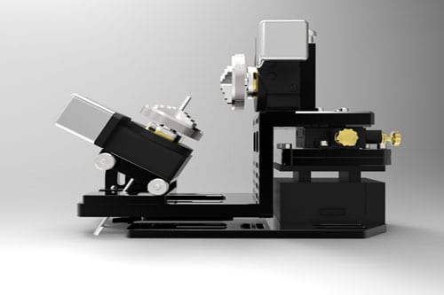
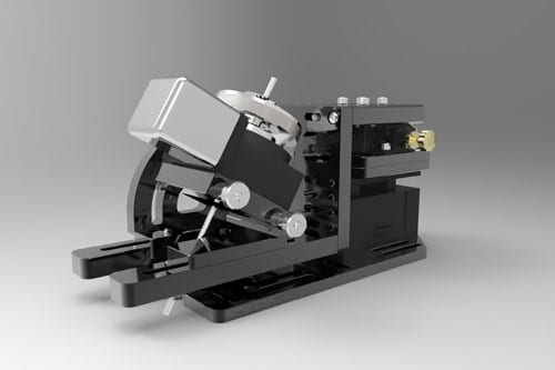
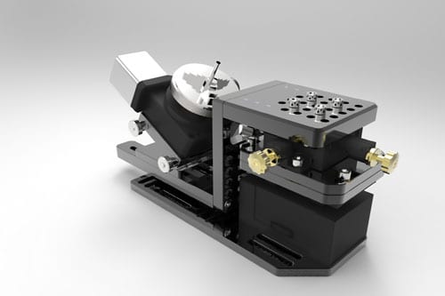
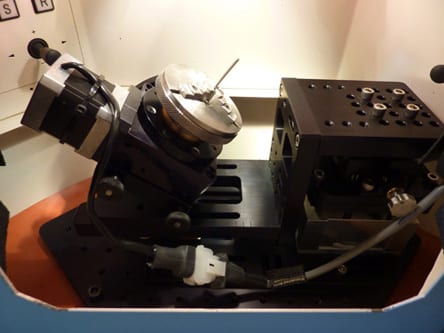
Laser welding stage with dual motors, one on top horizontal plate and one on the tilt plate. Comes standard with one motor.
FL2 Image 2
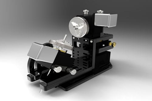
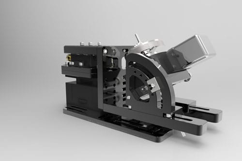
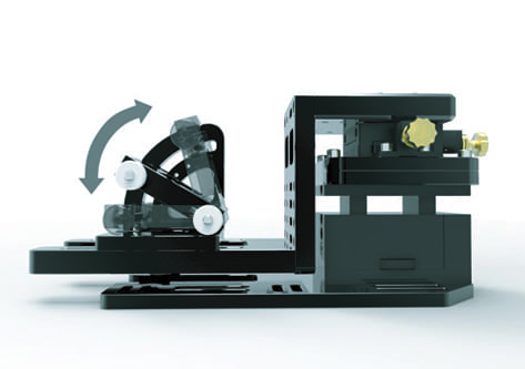
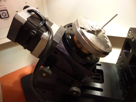
Tilt plate can be adjusted from horizontal spindle to vertical spindle and any position in between.
FL2 Image 3
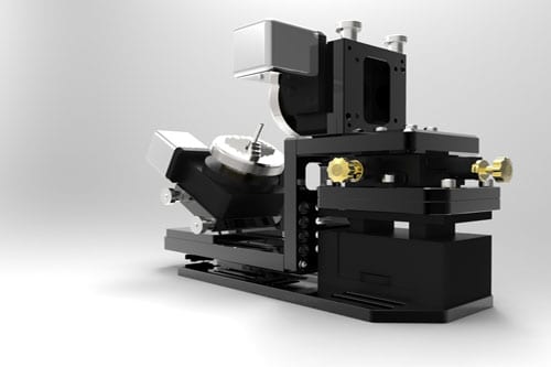
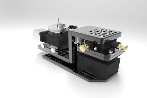
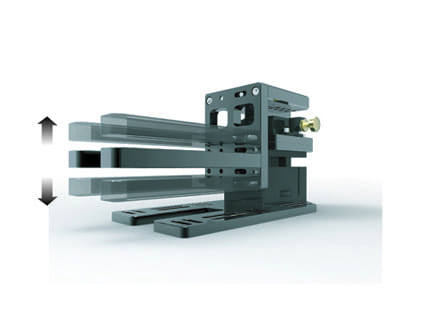
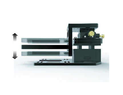
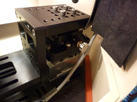
X, Y and Z stages adjust positions of both horizontal and tilt stages.
FL2 Image 4
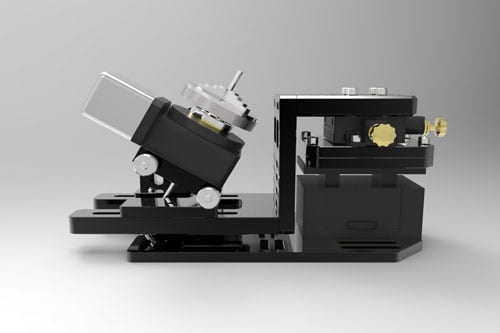
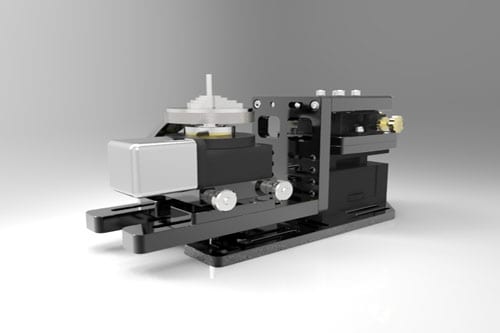
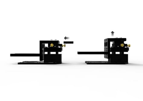
Standard configuration with one motor. Single motor can be mounted on top horizontal plate or on the tilt plate.
FL2 Image 5
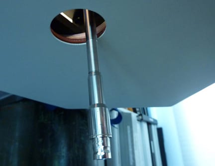
This is an important enabling feature: the tilt stage is designed to pass long tubes or shafts through the base plate, allowing components to be optimally positioned and welded to the the distal end of catheters.
FL2 Image 6
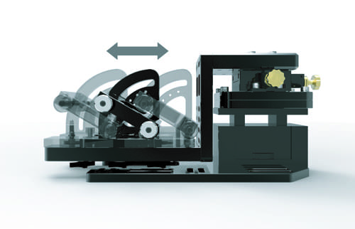
The tilt stage has the ability to slide along parallel rails and can be pin locked at 15 degree increments or clamp locked at any angle between spindle vertical to spindle horizontal.
FL2 Image 7
With the tilt stage set with the spindle vertical, a low profile position is obtained.
FL2 Image 8
The FL2 is designed for easy accees to adjustment knobs. For optimal alignment to your chamber or base plate, the FL2 has many areas where adjustments can be made to repostion mounting plates.
FL2 Image 9
The adjustable tilt stage is an extremely important feature for fixturing and providing access to component features where the angle of the laser beam needs to be positioned in a way that optimizes the light energy and reduces the distortion of the assembly.
FL2 Image 10
The FL2 has adjustability on the second stage tilt plate, allowing for optimal height positiong specific to you part or chamber needs.
FL2 Image 11
The right angle plate for the secondary tilt stage allows multiple positions.
FL2 Image 12
For optimal postioning of focal position and z-height range, an additional spacer block can be added under the x-y stage. This spacer is supplied with the system.
FL2 Image 13
The tilt stage for the FL2 can be adjusted from horizontal to vertical and any angle in between. In addition to setting any angle, there are hard stop locations every 15 degrees that can be locked with a pin.
FL2 Image 14
When is comes to setting the optimal angle and position, the tilt stage can also be traversed along the x axis, allowing for longer parts to be extended from the chuck.
FL2 Image 15
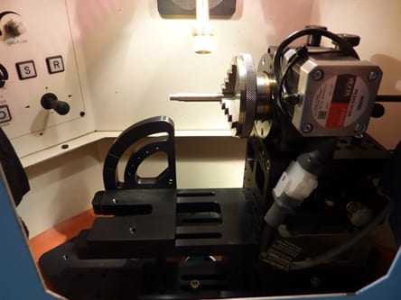
Inside the chamber, the FL2’s rotary head is mounted in the horizontal position. The thumb screws at the top of the rotary stage allow the motor to be easily moved from the horizontal to the vertical position.
FL2 Image 16
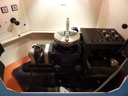
Inside the chamber, the FL2’s rotary head is mounted in the veritcal position (located on the tilt axis). The thumb screws at the top of the rotary stage allow the motor to be easily moved from the vertical to the horizontal position.
FL2 Image 17
Inside the chamber, the FL2’s rotary head is mounted in the angled position (located on the tilt axis). The thumb screws at the top of the rotary stage allow the motor to be easily moved from the vertical to the horizontal position.
FL2 Image 18
Adjusting the tilt of the rotary stage is easily accomplished by loosening the two thumb screws and moving the tilt plate to the desired position
FL2 Image 19
The X,Y and Z positions are easily situated on the right-hand side of the positioner.
FL2 Image 20
In this particular installation, the bottom of the chamber has been modified to pass an assembly up through the bottom and into the vertical postion of the rotary table. This is a useful capability to have when welding at the very tip of an assembly.
 ©Copyright 2026 Flashline-Tools.com All Rights Reserved.
For more information please Contact Us | Site Map