
FAQs: Rotary Laser Welding Devices
Pricing and placing an order?
Orders for our for our rotary laser welding devices can be placed directly through our website for US/Canada, South America, EU and Asia customers. Please click Contact for pricing and more information.
Lead time?
The standard lead time is 2-3 weeks after receipt of order.
Warranty?
Our systems are warranted against manufacturing defects for 12 months from time of purchase. We are dedicated to expediting repairs.
What makes Flashline stages better than similar systems?
First, our stages are designed for both the prototype developer as well as production jobs. We know from firsthand experience what is ideal for positioning both simple and complex jobs.
Second, the design of our systems has been carefully thought out to provide optimal positioning at critical angles. We have two systems: our ultra low profile system is for small shallow chambers and our multi-level, dual positioning system is for deep chambers. Our low profile FL1 stage is designed to integrate seamlessly into small closed chamber “glove box” type laser welders. However, the FL1 is very versatile and can be used in open frame systems as well.
Third, our stages use nothing but the best components. Our chucks are Swiss made, coming from the watchmaker’s industry. Other suppliers use inferior chucks which have extremely coarse actuation requiring wrench pins. The smooth operation of the chuck is very important when handling delicate jobs. Our chucks allow for a light touch to be applied when clamping down on parts. Chucks requiring higher torque to open and close will cause the system to move away from the set position; this is problematic in a production setting. Our linear and rotary components are also top end.
We take pride in offering the best micro welding stages at the most competitive price.
What specifically do your stages provide for medical device development?
There are two basic orientations that are used for welding round parts: horizontal and vertical. Additionally, any angle between these two orientations can be critical for achieving the optimal weld. Some devices may be attached to a long flexible or rigid portion. For this example, if the optimal weld is achieved while positioning in the vertical orientation, then passage of the device through the bottom of the chamber becomes necessary. We offer the only stages on the market where “through-hole” access is provided for the vertical orientation. To enable this access with your system, you would simply create an access hole in the bottom of your chamber, table or tooling plate. With this access open through the bottom of the chamber, the catheter can then be easily passed through and loaded into the chuck.
In addition to catheter development, through-hole access in the vertical orientation is a important attribute to have in your fixturing tool kit. Other customers are using our stages for assembly of sensors to long probes, fiber optics, fuel injectors, and electrical cables to micro connectors.
Is there any software required to operate your stages?
No. Our main goal is to provide the simplest most robust system that will endure many years of production without any issues or downtime. For the industries we support, one motorized rotary stage is going to cover most if not all of your laser welding needs.
How easy is it to operate your stages?
Since rotating small parts while welding is a primary operation in the assembly of micro components, we have made motorized rotation our main feature. The rotary stage is simply operated by a dial input for speed control. Parts can also be clamped in the low friction scroll chuck and traversed in X and Y manually for small linear welds. Additional fixturing can be purchased for clamping intricate components while performing spot or linear welds. Everything can tooled off of the 3 jaw scroll chuck.
How do you swap the motor from horizontal/tilt to the vertical position and vise versa?
The motor is easily swapped from one stage to another.
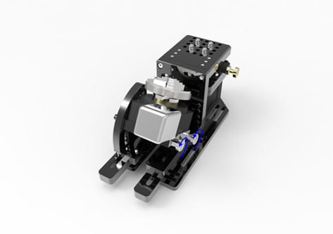
Simply loosen the two thumb screws located on the tilt stage.
Remove the screws, motor and T-nut from the tilt stage.
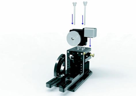
Position the motor and thumb screws on the horizontal plate. 
Lightly tighten the thumb screws.
How do you adjust the height of the z-axis for additional height?
There are two locations for making additional height adjustments.
You need to establish the proper height adjustments for your chamber. This is first established by setting the focus for the horizontal rotary stage. Insert a pin or tube in the the chuck and focus on the top surface of the pin by adjusting the z-axis thumb wheel. If you run out of z height or are close to the maximum z position, a spacer is included which you will use for adding addition height to the system.
Once you have optimized your z height for the main horizontal rotary position, you can then optimize the height location of the tilt platform. The height location of the tilt platform may change over time due to the geometry of your part.
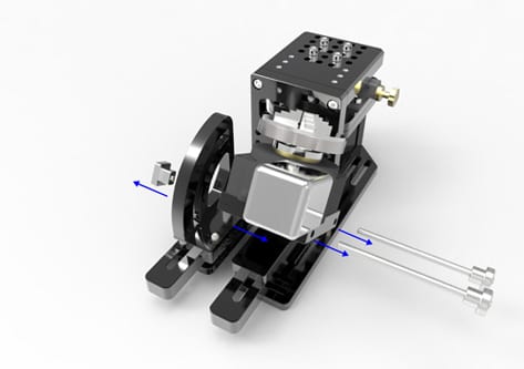
To add additional height to the z-axis, simply loosen and remove the four screws holding the horizontal plate to the x/y-axis, then insert the spacer and re-insert and tighten the four screws.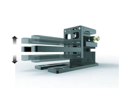
To adjust the height location of the tilt platform, remove the two screws holding the vertical plate to the main horizontal. Then from the back of the plate remove the screws holding the tilt platform to the vertical plate, select new location and re-tighten screws.
How do you adjust the position of the tilt stage?
The tilt stage has two degrees of freedom. The angle plate can be set to a horizontal or vertical position and any angle in between. It can also traverse along the x-axis.
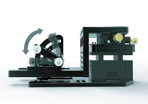
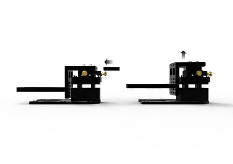
To adjust the tilt stage, simply loosen the two thumb screws, rotate the stage to the desired angle and re-tighten the tumb screws.
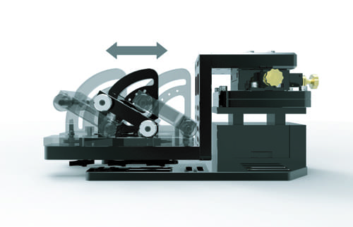
To traverse the position of the tilt stage along the x-axis, loosen the thumb screw at the bottom of the tilt base plate. Move to the desired position and tighten the thumb screw.
How do you set the angle plate with the locking pin?
The tilt stage can be pinned in place once the optimal position is determined. The stage can be pinned at angle increments of 15%. NOTE: the stage can also be locked in place with the thumb screw. Pinning the stage is a more assured way to keep it in position, especially in a production environment.

Shown above are the pin hole locations for inserting the pin. Also note the T-nut for locking the stage with or without the pin.
 ©Copyright 2026 Flashline-Tools.com All Rights Reserved.
For more information please Contact Us | Site Map